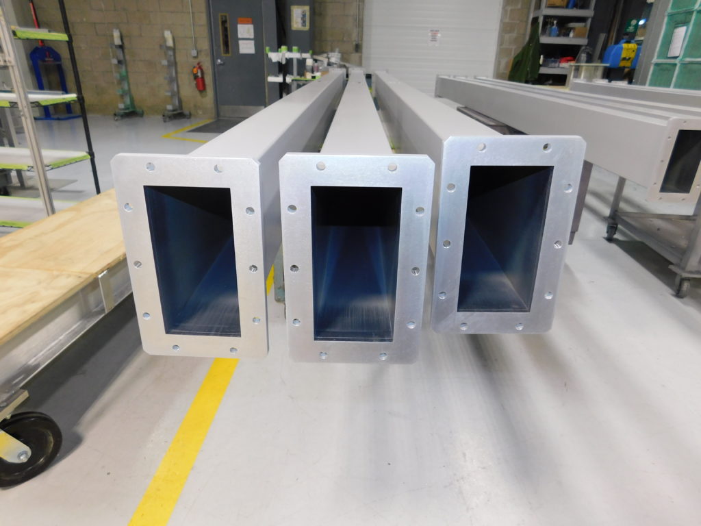
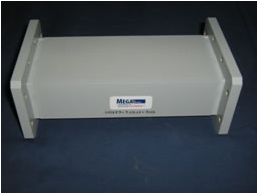
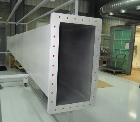
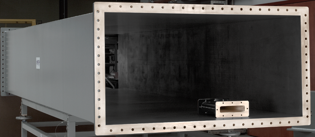
Mega Industries’ rigid waveguide straight sections are available in a variety of waveguide sizes. We also design and manufacture rigid rectangular tube. MEGA covers a variety of frequency ranges up to 40 GHz. Full and reduced height configurations are available to meet your requirements. High power waveguide section sizes through WR6200 are also available on special request.


View Rigid Waveguide 3D CAD Models and Capabilities on the Microwave Techniques website.
Mega Industries four-corner sprayarc argon® welding process is performed in precision fixtures on WR430 through WR2300. This ensures the highest quality waveguide, which is mechanically stable and designed for optimum electrical performance. We exceed EIA , IEC and Mil standards for both rectangular waveguide (IEC 60153-2, EIA RS-261, MIL-DTL-85 ) and cover flanges (IEC 60154-2, EIA RS-166, EIA RS-271, MIL-DTL-3922). Our standard models are commercial grade and military grade. For more information, please contact Mega Sales.
Request a Quote

Rectangular Waveguide Technical Data
| Size | Freq (GHz) | Cutoff TE10 Mode | Attenuation* | Peak Power (Megawatts)** |
| WR90 | 8.20 – 12.40 | 6.557 GHz | 5.542 / 3.83 | 0.474 / 0.33 |
| WR102 | 7.00 – 11.00 | 5.785 GHz | 4.27 / 2.98 | 0.68 / 0.48 |
| WR112 | 7.05 – 10.00 | 5.259 GHz | 3.99 / 2.76 | 0.73 / 0.52 |
| WR137 | 5.85 – 8.20 | 4.301 GHz | 2.91 / 2.00 | 1.12 / 0.79 |
| WR159 | 4.90 – 7.05 | 3.711 GHz | 2.19 / 1.48 | 1.66 / 1.18 |
| WR187 | 3.95 – 5.85 | 3.152 GHz | 1.79 / 1.23 | 2.15 / 1.52 |
| WR229 | 3.30 – 4.90 | 2.577 GHz | 1.27 / 0.86 | 3.46 / 2.44 |
| WR284 | 2.60 – 3.95 | 2.078 GHz | 0.953 / 0.652 | 5.0 / 3.5 |
| WR340 | 2.10 – 3.30 | 1.736 GHz | 0.702 / 0.475 | 7.6 / 5.4 |
| WR430 | 1.70 – 2.60 | 1.372 GHz | 0.494 / 0.334 | 12.2 / 8.6 |
| WR510 | 1.45 – 2.20 | 1.157 GHz | 0.382 / 0.259 | 17.1 / 12.09 |
| WR650 | 1.12 – 1.70 | 0.908 GHz | 0.266 / 0.188 | 27.8 / 19.6 |
| WR770 | 0.96 – 1.45 | 0.766 GHz | 0.206 / 0.140 | 39.1 / 27.6 |
| WR975 | 0.75 – 1.12 | 0.605 GHz | 0.145 / 0.098 | 62.6 / 44.2 |
| WR1150 | 0.64 – 0.96 | 0.513 GHz | 0.113 / 0.076 | 87.1 / 61.5 |
| WR1500 | 0.49 – 0.75 | 0.393 GHz | 0.076 / 0.051 | 148 / 104 |
| WR1800 | 0.41 – 0.62 | 0.328 GHz | 0.058 / 0.039 | 231 / 150 |
| WR2100 | 0.35 – 0.53 | 0.281 GHz | 0.046 / 0.031 | 290 / 205 |
| WR2300 | 0.32 – 0.49 | 0.256 GHz | 0.040 / 0.027 | 348 / 246 |
*Attenuation is in dB per 100 feet in aluminum
** Maximum / Minimum (1.25fc – 1.9fc)
Note: True theoretical values at 1 atmos. dry air 20° C, no safety factor included.

