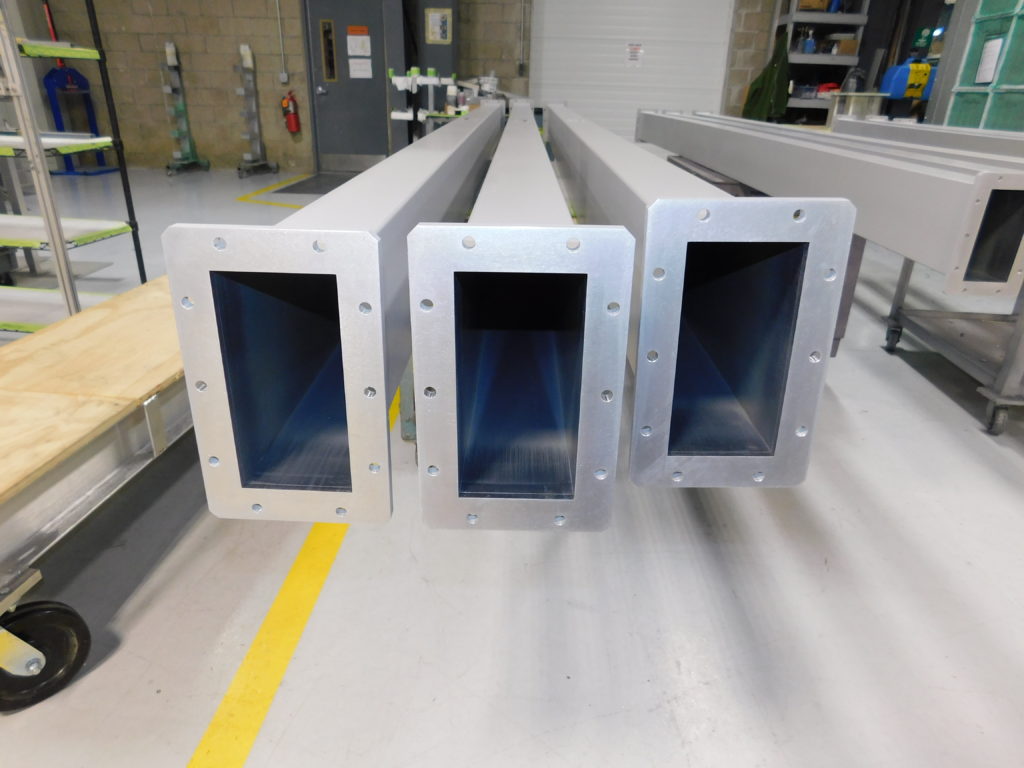
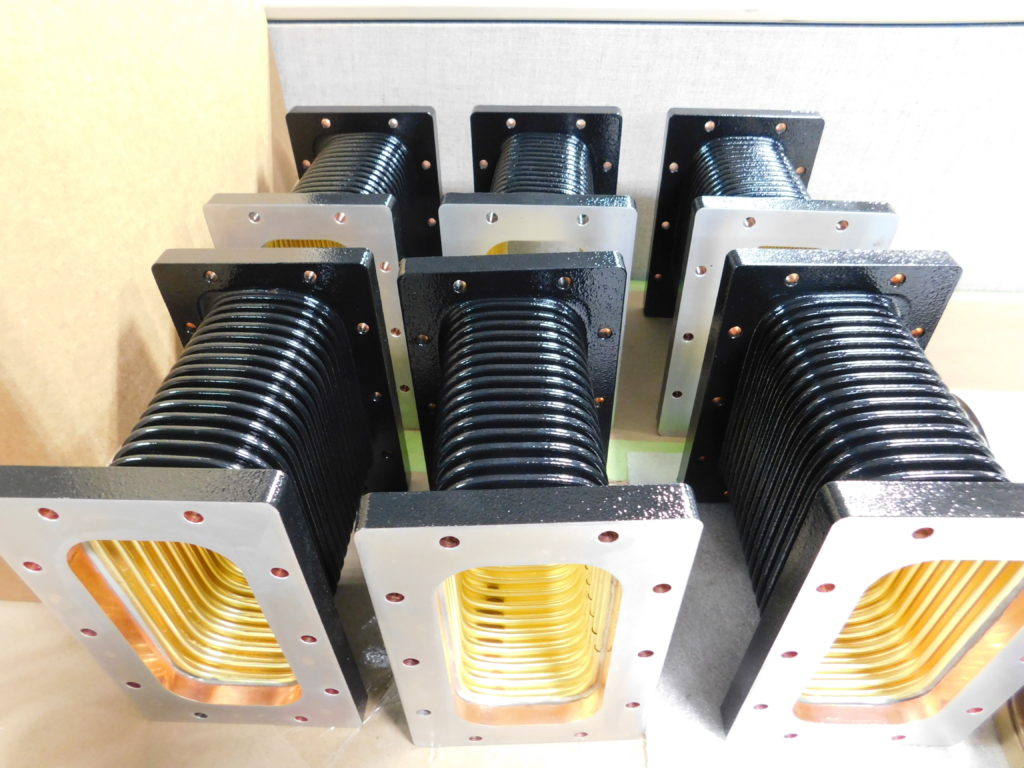
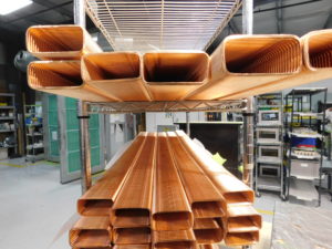
In microwave engineering, waveguides are transmission lines used to guide electromagnetic waves at specific frequencies. In the case of Microwave Techniques, two types of rectangular transmission line are manufactured: rectangular rigid waveguide and rectangular flexible waveguide. The latter of which is also known by its portmanteau of “flexguide.”
In determining when to utilize rigid or flexible waveguide, several factors are relevant. Application, RF power level, frequency, material cost, mechanical advantages, system interface design and assembly orientation all play a role in selection.
In designation of size for rigid and flexible waveguide, microwave engineers use the “WR” short form, which stands for “Waveguide Rectangular.” Each WR designation corresponds with a number, indicative of the waveguide dimensions for the inner width.
This applies to both flexible and rigid. For example, a WR284 flexible waveguide section has an inner dimensional width of 2.84 inches. Likewise, a WR650 rigid waveguide section has an inner dimensional width of 6.50 inches.
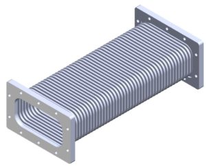
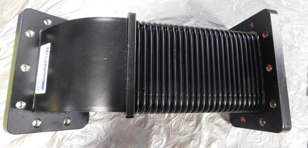
Rigid Rectangular Waveguide Rectangular Flexible Waveguide
Applications
Rigid and flexible waveguides are utilized across several markets. These include commercial and military radars, satellite communications, industrial microwaves, medical linear accelerators, and high-energy physics research. Each of these sectors make use of rectangular waveguides, among other passive microwave components for critical applications. From food processing to oncology treatment, to weather and defense radar systems – waveguides are a component of everyday life.
The military utilizes both styles of rectangular waveguide. Both are used in airborne, naval, and ground-based radar systems across several frequency bands. Waveguides are useful for signal transmissions across the S, C and X-Bands. Applications include security operations and inspection by border control, for baggage and cargo screening.
Waveguides are also found in directed energy weapons (DEW’s). DEW’s use highly focused energy, such as microwaves, to detect, track and scan targets by focusing pulses of radar energy. DEW’s focus on missiles and other projectiles, vehicles, electronic and optical devices.
Similarly, rigid and flexible waveguides can be used in satellite communication (Satcom) applications for commercial radar systems and antenna feed networks. Many Satcom applications have strict mechanical layouts and stringent electrical designs. In Satcom applications where movement is a factor, flexible waveguides give extra flexibility in space constraints. Flex sections simultaneously couple with other waveguide flanges, without altering the mode of the signal.
In scientific applications, physicists and engineers make use of both rigid and flexible waveguide. Many test laboratories engage in research pursuits that demand microwave energy. Synchrotrons, light sources, particle accelerators, and linear accelerators (LINAC’s) each undergo facility wide and system specific upgrades.
These upgrades allow scientists to keep up with the demanding nature of high-energy physics and nuclear fusion research. During system upgrades and facility expansions, passive microwave components are employed in areas with space constraints and specific mechanical requirements.
It is common to see runs of both types of rectangular waveguide – rigid and flex – in long “runs” of waveguide. In conforming to stringent requirements, laboratories utilize shorter lengths of flexguide in their waveguide runs. These sections ease the vibration and support other mechanical movements of the RF systems. These runs are lengthened throughout the labs, spanning from the Microwave Source (Klystron or Solid-State Amplifiers) to the cavity.
In the industrial sector, microwave systems process a wide range of materials, from frozen foods to wood pulp to plasma. These systems employ waveguides to transmit microwave power to temper, dry, cook, and heat materials.
Given that cost can be a driving factor, rigid waveguides are used more commonly than flex in industrial microwave systems. This is large in part because rigid waveguides tend to be more economical with higher transmission capabilities. These two factors are essential in materials processing.
The complete industrial microwave system shown below demonstrates the use of rigid waveguides, which connect the generator to the applicator. For the short length shown below, flex is not required. However, for longer runs it may be necessary to install flex somewhere to handle thermal expansion.
In medical applications, S-Band (WR284, R32) microwave components are developed for use in medical linear accelerators (LINACs). In the treatment of tumors, medical physicists and engineers operate medical LINACs. The LINACs produce high-energy x-rays for use in external beam radiation, delivering treatments for patients with cancer. Here, microwave energy is engaged in a way that has potential to destroy cancer cells.
As cancer research and oncology treatment expand, Microwave Techniques regularly develops products specific to the needs of medical LINAC systems. The waveguide assembly shown below is used in medical research and is comprised of both rigid and flex.
Material Selection & Construction
The engineering design, manufacturing process, and general construction of waveguide sections vary, depending upon whether flexible or rigid is required. In both cases, lengths can be manufactured as straight sections, bends, twists, and other assemblies, or as unflanged waveguide tube.
Straight sections of either style typically have flanges on both ends. Assemblies may contain other attached components. Tube consists of neither extra components nor flanges.
Typically, flanged and raw tube sections of waveguide are manufactured from 6061-T6 aluminum alloy or copper. Other materials include brass and phosphor bronze alloys. To provide optimum VSWR, no energy leakage and maximum power handling capabilities, flanges and gaskets are offered in numerous configurations. This includes IEC, EIA, and MIL specifications to suit customer needs.
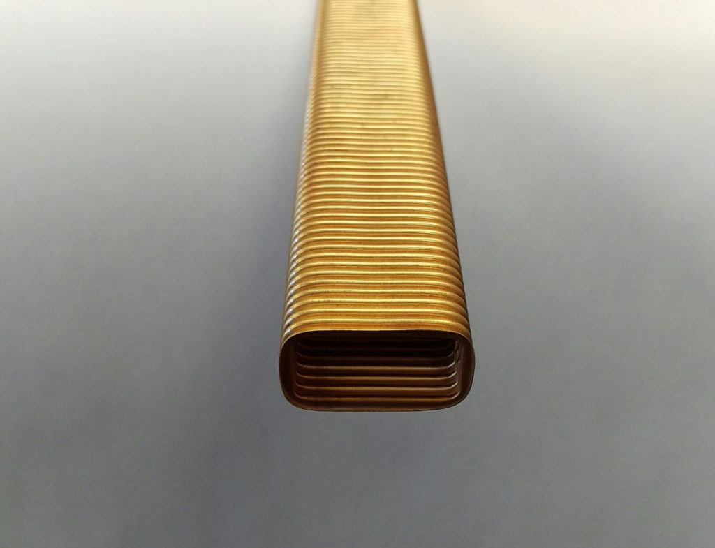
Currently, the only flexible waveguide Microwave Techniques manufactures using seamless tube is WR90, as seen below. Microwave Techniques manufactures all other sizes using flat sheet, which is then welded into a tube.
The weld process is refined to the point that it is comparable to seamless, as seen in the WR229 design. In the designs greater than WR284, up through WR650, a single sheet with one braze seam is constructed. The braze seam is offset from the center of broadwall.
Larger sizes have two braze seams, both are offset from the center of the broadwall. The offset is critical because the center of the broadwall is where peak voltage occurs. Here, it is preferred to have any imperfections moved away from this point to increase power handling.
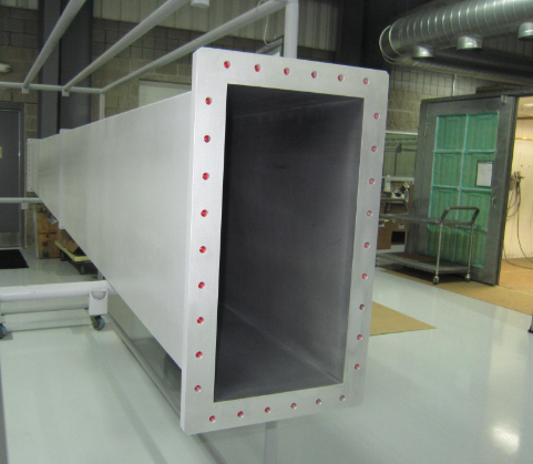
Brazing Flexible Waveguide WR90 Flexguide Tube WR1800 Rigid Waveguide
In the past, many flexible waveguide parts were constructed using Beryllium Copper (Alloy 172, BeCu). This was initially convoluted from a flat strip. It was later bent to form a rectangular shape.
Subsequently, this formed shape was then brazed to provide a flexible, rectangular waveguide tube. However, as power levels increased, the braze seam on the broad wall was determined to be problematic due to arcing events.
The center seam design was deemed to have inadequate power handling. The updated design with a seam on the narrow wall demonstrated better power handling.
Many alloys of Copper do not exhibit this quality. They simply can only be annealed with heat, then would harden. Lastly, they could potentially crack if repeatedly strained.
The transition away from Beryllium Copper was also the result of recognizing Beryllium’s cancerous characteristics. Beryllium Copper was also used in the past because it could be heat-treated, giving the material a spring-like temper. Now, phosphor bronze can be procured with a specific temper, making it acceptable for use in flexible waveguides.
With the latest edition of MIL-DTL-287, numerous jacketing styles are allowed, including Silicone, now replacing Neoprene. Microwave Techniques latest design exhibits the same electrical and mechanical qualities as the original Beryllium Copper design.
Lengths of flex tube Inside look of a flex bend
Compressed Convolution of Flex
Microwave Techniques offers a “compressed convolutions” version of traditional flexible waveguide. This unique waveguide offers excellent electrical performance, while giving that extra flexibility in tight connections that certain layouts may demand. The convoluting process allows for increased movement in both the E and H plane. It requires less force for compression and expansion.
As a result of this unique compression technique, the flexguide offers greater expansion capabilities. It also offers slightly less compression than the standard flexible waveguide. Overall, this enhanced capability provides a softer and more forgiving section. This proves extremely valuable in areas that would normally make for a difficult connection.
Finally, the updated process of brazing the seam off-center assures excellent electrical performance for high-power applications. By brazing, and not joining by epoxy, we see a strengthened and longer life on the joint. The joint is less prone to splitting from pressure of Microwave (MW) or Radio Frequency (RF) Energy.
Benefits of Flexible Waveguide
One of the benefits of utilizing flexible versus rigid waveguide is the superior mechanical advantages. Many times, flexguide is used to permit mechanical movement caused by thermal expansion. In some instances, flex is employed for vibration isolation. In settings where expansion and contraction in a microwave feed must be absorbed, flex is recommended.
Although eleventh-hour alterations are uncommon in planned installations, these rare occasions also warrant the use of flex. In such an event, it may be necessary to modify a waveguide section during an installation. It may be beneficial to design a flexible waveguide section at the end of a long run. This alleviates the need for excessive geometric tolerancing of the entire line.
Simply taking up any uncertainty in overall length with one section of flexible waveguide can reduce overall system cost. Restoring a portion of a run and replacing with flexible waveguide parts may be timelier than dismantling an entire system. It will likely cost less, as well.
Furthermore, a distinct advantage of utilizing flexguide is its weight reduction. This is true, given all other mechanical features (material, length, flange style, paint, jacketing) remain the same. One example wherein weight may not be reduced, is comparing brass flex to aluminum rigid. In shorter lengths, the flange weight may dominate the overall weight of the structure.
A final scenario in which flexible waveguide proves useful, is to account for either offset or angular system flange misalignments. In such an event, a pre-formed bend of a flex section may serve a more effective purpose than rigid waveguide. Each style of flexible waveguide (straight sections, sweeps, twists, offsets) serves a distinct purpose. Each distinct design possesses its own associated benefits.
Benefits of Rigid Waveguide
The benefits of rigid waveguides are typically related to electrical performance, whereas flex may have more of a mechanical advantage. The rigid style commonly has greater transmission characteristics and higher power handling capabilities than flex.
When it comes to material selection, choices are greater with rigid waveguide. Aluminum, copper, stainless steel, and more can be manufactured into rectangular rigid waveguide. This contrasts to flexguide, which must be made from materials that are readily formed.
Generally, systems are manufactured from as much rigid line as possible. Flex is used only at the end to take up thermal expansion or other movement as required.
Another performance factor that may contribute to a decision between choosing flex and rigid is temperature. Additionally, insertion loss for rigid waveguide is lower than that of flexible waveguide. As its name implies, rigid tends to be stronger and able to withstand harsher environments.
However, this is where jacketing and sealing are critical. Environmental factors such as humidity, moisture, or other contaminants may impact the performance of the waveguide.
In nautical or coastal applications, antenna and radar systems are likely at higher risk than would exist on land. Waveguides are susceptible to moisture ingress and corrosion contamination. Here, it is evident that the materials of a rigid waveguide may prove useful in a harsh environment.
Overall, rigid waveguide may be considered more optimal for its characteristics involving electrical performance. These factors include insertion loss, leakage of electromagnetic energy and temperature management.
Summary
The benefits of flexible waveguide include:
- To permit mechanical movement caused by thermal expansion
- To account for system flange misalignment
- Useful for vibration isolation
- Weighs less than rigid, given all other mechanical features remain the same
- Allows for expansion and contraction
- Easier to install or replace when modifying or dismantling sections of a waveguide run
The benefits of rigid waveguide include:
- Greater transmission characteristics
- Lower insertion loss
- Elevated power handling capabilities
- Wider range of options for material selection
- Higher tolerance for withstanding temperature change (high and low)
Conclusion
Flexible waveguide proves its value best in situations where mechanical positioning is of the utmost importance. Flex is commonly employed in overhauls of existing systems and first-time installations. While flexible waveguide has electrical performance limitations, the mechanical benefits often offset those limitations when necessary. In the event of layout misalignment, flexible waveguide offers the ability to bend and stretch where rigid waveguide may fall short.
Flexible waveguide is generally only used where necessary because of its higher insertion loss compared to rectangular rigid waveguide. Several mechanical, environmental, and electrical factors must be considered when deciding between flexible and rigid waveguide. Factors to consider include thermal expansion, vibration, electrical loss characteristics and mechanical movement.
Download the PDF version here:

