Mega manufactures a full line of flexible waveguide products. Our line includes: straight sections, offsets, sweeps and flexible twists in an array of waveguide sizes. Mega also offers half height and custom sizes upon request.
Mega’s designs are field proven to meet the highest standards in the industry with material options including aluminum or copper alloys. Standard flex product finish is a chemical resistant epoxy paint system. Urethane and neoprene jacketing systems are also offered.
In the production process we use a process of brazing the seam off-center. This assures excellent electrical performance for high power applications. It also improves joint longevity and eliminates the potential for splitting or leaking. See the table below for power levels and typical bending radius.
View Flexible Waveguide 3D CAD Models and Capabilities on the Microwave Techniques website.
-
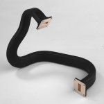
Flexible Waveguide Offsets
-
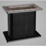
Flexible Waveguide Straights
-
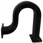
Flexible Waveguide Sweeps
-
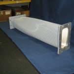
Flexible Waveguide Twists
Flexible Waveguide Technical Data
| Size | Frequency (GHz) | VSWR* | Attenuation** | Avg. Power (kW) | Peak Power (MW) |
| WR90 | 8.20 – 12.40 | 1.10 | 0.09 | 3 | 0.18 |
| WR102 | 7.00 – 11.00 | 1.10 | 0.08 | 4 | 0.30 |
| WR112 | 7.05 – 10.00 | 1.09 | 0.06 | 4 | 0.31 |
| WR137 | 5.85 – 8.20 | 1.09 | 0.05 | 5 | 0.50 |
| WR159 | 4.90 – 7.05 | 1.08 | 0.04 | 5 | 1.10 |
| WR187 | 3.95 – 5.85 | 1.08 | 0.03 | 6 | 1.25 |
| WR229 | 3.30 – 4.90 | 1.07 | 0.02 | 8 | 1.55 |
| WR284 | 2.60 – 3.95 | 1.09 | 0.02 | 10 | 2.00 |
| WR340 | 2.20 – 3.30 | 1.08 | 0.01 | 16 | 3.70 |
| WR430 | 1.70 – 2.60 | 1.07 | 0.01 | 20 | 4.70 |
| WR510 | 1.45 – 2.20 | 1.07 | 0.01 | 20 | 4.70 |
| WR650 | 1.12 – 1.70 | 1.06 | 0.01 | 150 | 11 |
| WR770 | 0.96 – 1.45 | 1.05 | 0.01 | 210 | 15 |
| WR975 | 0.75 – 1.12 | 1.05 | 0.01 | 350 | 25 |
| WR1150 | 0.64 – 0.96 | 1.05 | 0.01 | 490 | 35 |
| WR1500 | 0.49 – 0.75 | 1.05 | 0.01 | 840 | 60 |
| WR1800 | 0.41 – 0.62 | 1.05 | 0.01 | 1200 | 86 |
| WR2100 | 0.35 – 0.53 | 1.05 | 0.01 | 1300 | 117 |
| WR2300 | 0.32 – 0.49 | 1.05 | 0.01 | 1540 | 141 |
*VSWR is per 2 foot section
**Attenuation is in dB per foot

Bending Radius to Centerline
| Size | E-Plane w/ Jacket | H-Plane w/ Jacket | E-Plane No Jacket | H-Plane No Jacket |
| WR90 | 1.75″ | 2.50″ | 1.25″ | 1.50″ |
| WR102 | 2.00″ | 2.88″ | 1.30″ | 1.94″ |
| WR112 | 2.25″ | 3.25″ | 1.40″ | 1.82″ |
| WR137 | 2.38″ | 3.38″ | 1.50″ | 2.07″ |
| WR159 | 4.00″ | 6.00″ | 1.60″ | 2.25″ |
| WR187 | 4.38″ | 6.50″ | 1.94″ | 3.00″ |
| WR229 | 6.50″ | 8.00″ | 2.13″ | 3.25″ |
| WR284 | 7.00″ | 9.50″ | 2.94″ | 5.50″ |
| WR340 | N/A | N/A | 4.25″ | 6.00″ |
| WR430 | N/A | N/A | 6.00″ | 8.00″ |
| WR510 | N/A | N/A | 6.00″ | 12.00″ |
| WR650 | N/A | N/A | 6.00″ | 12.00″ |
| WR770 | N/A | N/A | 6.00″ | 12.00″ |
| WR975 | N/A | N/A | 9.00″ | 18.00″ |
| WR1150 | N/A | N/A | 12.00″ | 24.00″ |
| WR1500 | N/A | N/A | 12.00″ | 30.00″ |
| WR1800 | N/A | N/A | 18.00″ | 36.00″ |
| WR2100 | N/A | N/A | 24.00″ | 42.00″ |
| WR2300 | N/A | N/A | 24.00″ | 48.00″ |
Products
Offsets

Mega’s flex offsets have excellent electrical performance. Offsets give you extra flex that your high power application may demand.
Straights
Our flexible straight sections are manufactured from aluminum, copper, brass and phosphor bronze. Also, various flange designs are supplied to meet EIA and Military specs.
Sweeps
Sweeps are manufactured from various materials and various flange layouts. Mega provides full design services for factory formed sweeps that assure accuracy and electrical performance.
Twists
Flex Twists are manufactured from aluminum, copper brass and phosphor bronze with various flange styles. We provide full design services for factory formed bends and twists to assure accuracy and electrical performance. A ten percent (10%) operating frequency bandwidth is requested to provide optimum VSWR results.
Material Selection
In the past, many flexible waveguide parts were constructed using Beryllium Copper Coil (Alloy 172). This was initially convoluted from a flat strip. It was later bent to form a rectangular shape. Subsequently, this formed shape was then brazed to provide a flexible rectangular waveguide tube.
As power levels increased, the braze seam on the broad wall was determined to be problematic due to arcing events. This resulted in the development of a seamless Phosphor Bronze design as Beryllium Copper concerns increased. The new design exhibits the same qualities as the original Beryllium Copper Design. Numerous Jackets are allowed by the latest edition of MIL-DTL-287 and Neoprene is now replaced by Silicone.

Compressed Convolution
Our convolution process allows for increased movement in both the E and H plane. In addition, it requires less force for compression and expansion. As a result of the unique compression technique, this waveguide will offer greater expansion ability.
This enhanced capacity yields a softer section that can prove extremely valuable. Especially in areas that would normally make for a difficult connection.
Compressed Convolution Typical Data
| Size | Frequency (GHz) | VSWR* | Attenuation** | Avg. Power (kW) | Peak Power (MW) |
| WR650 | 1.12 to 1.70 | 1.06 | 0.01 | 150 | 11 |
| WR770 | 0.96 to 1.45 | 1.05 | 0.01 | 210 | 15 |
| WR975 | 0.75 to 1.12 | 1.05 | 0.01 | 350 | 25 |
| WR1150 | 0.64 to 0.96 | 1.05 | 0.01 | 490 | 35 |
| WR1500 | 0.49 to 0.75 | 1.05 | 0.01 | 840 | 60 |
| WR1800 | 0.41 to 0.62 | 1.05 | 0.01 | 1200 | 86 |
| WR2100 | 0.35 to 0.53 | 1.05 | 0.01 | 1300 | 117 |
| WR2300 | 0.32 to 0.49 | 1.05 | 0.01 | 1540 | 141 |
*VSWR is per 2 foot section
**Attenuation is in dB per foot


